Microcontrollers 1: Finite State Machines
Lecture Contents
- The Challenge: Doing multiple things at once.
- The Problem with
delay(): Understanding blocking code. - A Better Way: Non-blocking timing with
millis(). - Introduction to State Machines: Theory and diagrams.
- Practical Example: Modelling an elevator.
- Implementation: Using
enum classandswitchstatements. - Key Takeaways.
The Challenge: Doing More Than One Thing
How can we make an Arduino perform multiple tasks seemingly at the same time?
For example, how do we flash two LEDs at completely independent rates?
- One LED flashes slowly.
- Another LED flashes very quickly.
The standard "Blink" sketch teaches a technique that makes this simple task very difficult.
The Beginner's Approach: The Blink Sketch
Every Arduino journey starts with the "Blink" example. It's a great milestone, proving the connection between your code, the board, and the electronics.
However, the coding technique it uses is not optimal for more complex projects.
Let's look at the core logic.
#define RED_LED_PIN 10

void setup() {
  pinMode(RED_LED_PIN, OUTPUT);
}

void loop() {
  digitalWrite(RED_LED_PIN, HIGH);
  delay(500);
  digitalWrite(RED_LED_PIN, LOW);
  delay(500);
}
The Problem with delay()
The delay() function is a blocking function.
This means that while the Arduino is in a delay(), it can do absolutely nothing else.
- The microcontroller is busy doing nothing.
- It cannot read sensors.
- It cannot check for button presses.
- It cannot update a screen.
- It cannot run any other code.
Your program is completely frozen for the duration of the delay. This is suboptimal for any responsive system.
Attempting Two LEDs with delay()
What happens if we just combine the blink logic for two LEDs into the main loop?
We want them to blink independently, but the result is very different.
The code becomes sequential. One LED must complete its entire on-off cycle before the next one can even start.
void loop() {
  // Red LED flashes slowly
  digitalWrite(RED_LED_PIN, HIGH);
  delay(500);
  digitalWrite(RED_LED_PIN, LOW);
  delay(500);

  // Green LED flashes quickly
  digitalWrite(GREEN_LED_PIN, HIGH);
  delay(100);
  digitalWrite(GREEN_LED_PIN, LOW);
  delay(100);
}
Why It Doesn't Work
The code is executed sequentially. The green LED code cannot run while the red LED code is running, especially while it's paused in a delay().
- Turn red LED on.
- Wait 500ms. (Green LED can do nothing).
- Turn red LED off.
- Wait 500ms. (Green LED can do nothing).
- Turn green LED on.
- Wait 100ms.
- Turn green LED off.
- Wait 100ms.
- Repeat.
They are not independent. The green LED is waiting on the red LED. We need a non-blocking way to handle time.
The Solution: Non-Blocking Timing with millis()
The Arduino has a built-in function called millis().
- It returns the number of milliseconds since the board was powered on.
- It's a continuously running timer (an unsigned long).
- It does not stop the program.
Instead of saying "wait for X milliseconds", we can change our logic to "check if X milliseconds have passed".
This allows the loop() to run continuously and quickly, checking on different tasks each time through.
The millis() Pattern
The core logic for non-blocking delays involves three main elements:
- A variable to store the last time an event happened (
previousMillis). - The desired interval between events (
interval). - A check inside the
loop().
This pattern lets the loop run freely. The code inside the `if` statement only executes when the time is right.
unsigned long previousMillis = 0;
const long interval = 1000;

void loop() {
  unsigned long currentMillis = millis();

  if (currentMillis - previousMillis >= interval) {
    // Save the last time you did something
    previousMillis = currentMillis;

    // Do something here (e.g., toggle an LED)
  }
  // Other code can run here without waiting!
}
New Code Structure
We break our tasks into separate functions.
The main loop() becomes very simple. Its only job is to call these functions repeatedly and as fast as possible.
Each function is responsible for deciding for itself if it's time to act, using the millis() pattern.
// setup() remains similar, setting pinMode for both LEDs

void loop() {
  blinkRedLED();
  blinkGreenLED();
  // We can add more functions here!
}

void blinkRedLED() {
  // Red LED logic goes here
}

void blinkGreenLED() {
  // Green LED logic goes here
}
Code Deep Dive: blinkRedLED()
This function contains all the logic for the red LED.
- A `static` variable holds the previous time.
- The `if` statement checks if 500ms have passed.
- If true, it toggles the LED's state.
- It then updates the timestamp.
Most of the time this function is called, the `if` condition is false, and it returns instantly.
void blinkRedLED() {
  static unsigned long redMillis = 0;
  const long redInterval = 500;

  if (millis() - redMillis >= redInterval) {
    redMillis = millis();

    // Toggle the LED state
    bool currentState = digitalRead(RED_LED_PIN);
    digitalWrite(RED_LED_PIN, !currentState);
  }
}
The `static` Keyword
In this context, the keyword static is crucial.
static unsigned long redMillis = 0;
- Initialised Once: This line is only executed the very first time the function is called.
- Retains Value: The variable
redMilliskeeps its value between function calls. If it were not static, it would be reset to 0 every time the function was called, and our timer would never work.
It creates a persistent variable that is only accessible within the scope of that function, which is good programming practice (avoids global variables).
Code for blinkGreenLED()
The function for the green LED is identical in structure to the red one.
The only difference is that it uses its own `static` timer variable and a different interval (100ms).
Because each function manages its own time, they do not interfere with each other.
void blinkGreenLED() {
  static unsigned long greenMillis = 0;
  const long greenInterval = 100;

  if (millis() - greenMillis >= greenInterval) {
    greenMillis = millis();

    // Toggle the LED state
    bool currentState = digitalRead(GREEN_LED_PIN);
    digitalWrite(GREEN_LED_PIN, !currentState);
  }
}
Is This a State Machine?
We've achieved our goal of running two tasks independently. This is a huge step forward!
Is it a true Finite State Machine (FSM)? Not quite.
- We have an implicit state (the LED is either on or off), which we check with
digitalRead(). - But we don't have an explicit variable that tracks the overall state of our system.
This technique is the first, crucial step towards building a proper state machine. For many simple tasks, this is all you need. For more complex logic, we need to be more formal.
What is a Finite State Machine (FSM)?
An FSM is a model used to design computer programs and digital logic.
- It can be in one of a finite number of states at any given time.
- The machine can change from one state to another in response to some external inputs; this change is called a transition.
- A machine can only be in one state at a time. This is the current state.
FSMs are a powerful way to manage complex behaviour in a clear, organised, and non-blocking way.
State Diagrams: Visualising FSMs
Before writing any code, it's best to visualise the FSM with a State Diagram.
- States are represented by circles.
- Transitions are represented by arrows between states.
- The condition or action that causes the transition is written alongside the arrow.
- A starting point indicates the initial state.
This diagram becomes the blueprint for your code.
Simple Example: A Light Bulb
A simple light switch has two states: OFF and ON.
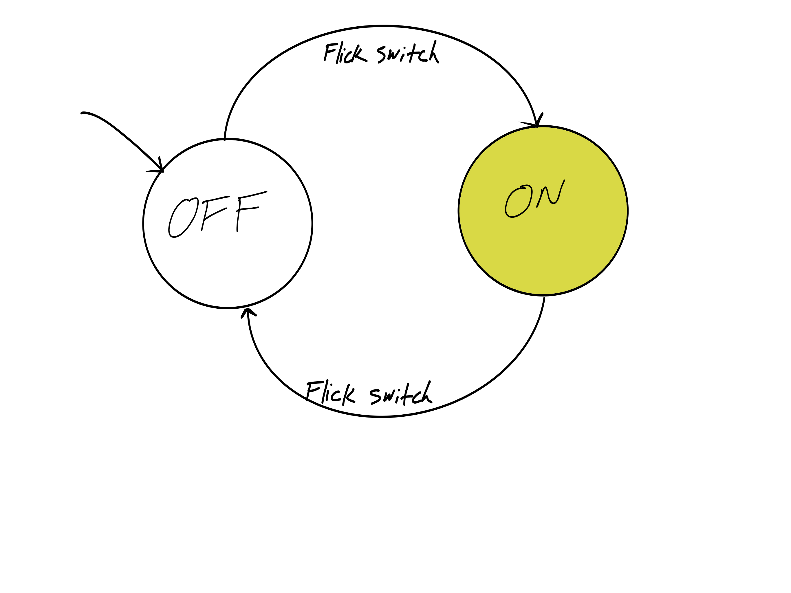
The action "Flick Switch" causes a transition from the current state to the other state.
More Complex Example: Traffic Light
A traffic light cycles through states based on timers.
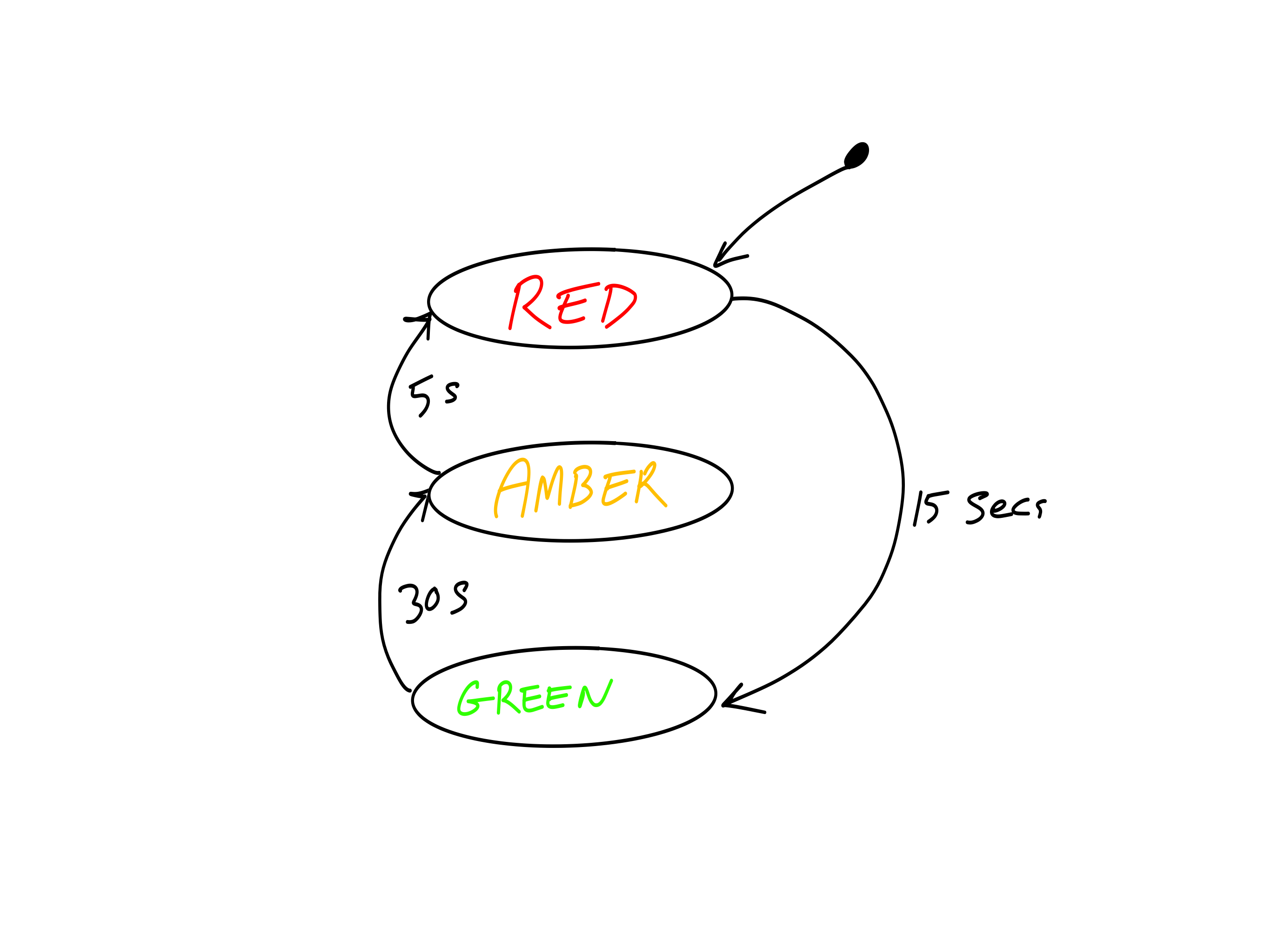
The transitions are triggered by time elapsing, not a direct user input.
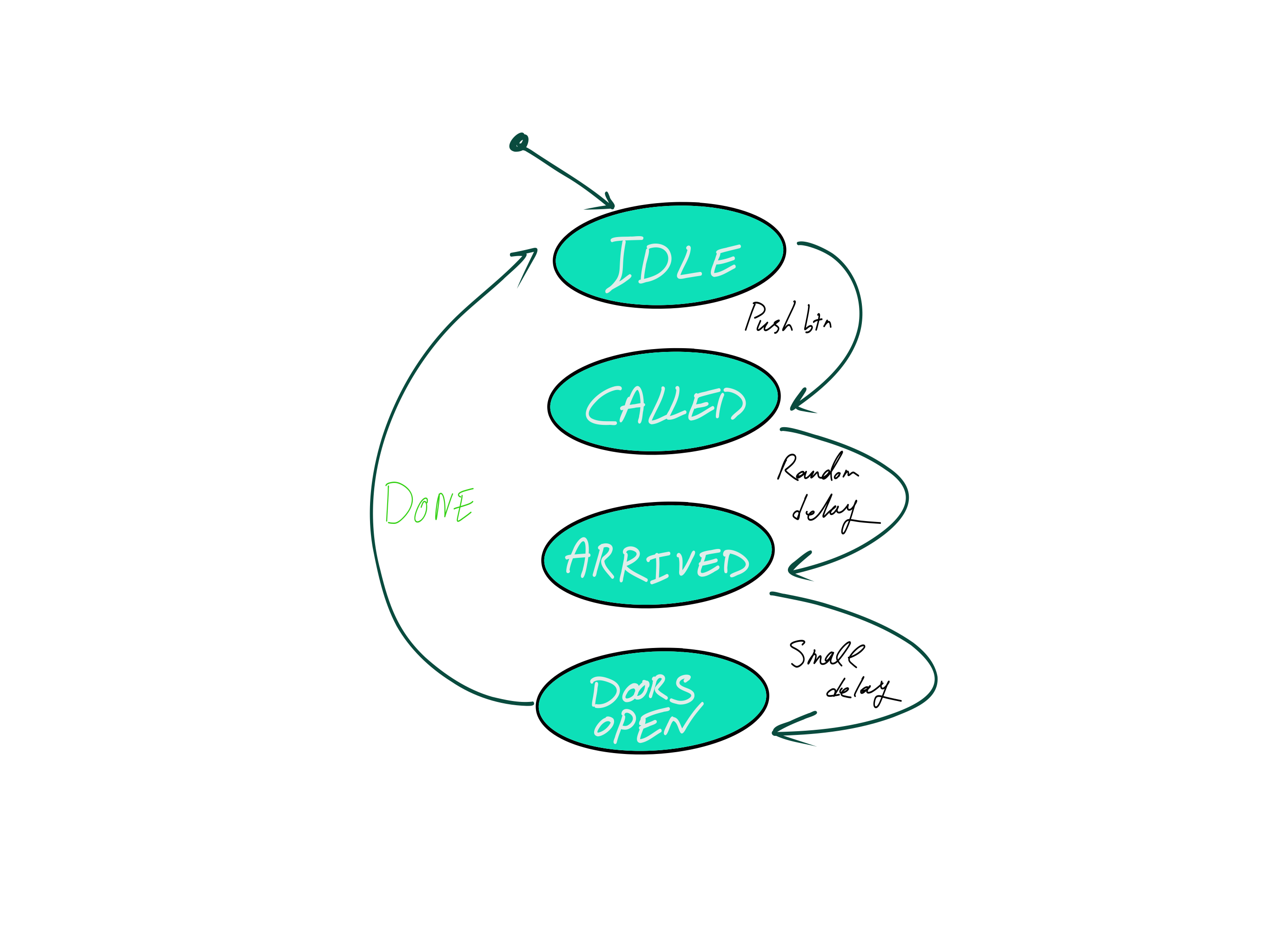
Our Project: A Simple Elevator FSM
We will model a simple elevator call button system.
The sequence of events is:
- The system starts Idle, waiting.
- A user presses a button, the lift is Called.
- After a random delay, the lift has Arrived.
- The doors Open (indicated by a beep).
- The system returns to the Idle state.
Let's map this to a state diagram.
The Elevator State Diagram
Step 1: Defining States with enum class
We use an enum class to define our states. This is a modern C++ feature available in Arduino.
Benefits:
- Type Safety: Prevents accidentally assigning an invalid integer value to our state variable.
- Readability: The code is self-documenting. `ElevatorState::Idle` is much clearer than `0`.
// Define all possible states for our FSM
enum class ElevatorState {
  Idle,
  Called,
  Arrived,
  DoorsOpen
};
Step 2: The State Variable
We need a variable to keep track of the machine's current state.
Just like our `millis()` timers, it needs to be static so it remembers its value each time the function is called.
We initialise it to our starting state, which is `Idle`.
// Inside our elevator control function

// Declare a static variable of our new type
// and set its initial state.
static ElevatorState currentState = ElevatorState::Idle;
Step 3: The switch Statement
The switch statement is the heart of the FSM. It's a clean way to execute different code for each possible state.
Inside our main elevator function, we switch on the `currentState` variable.
Each case corresponds to one of the states we drew in our diagram.
void handleElevator() {
  static ElevatorState currentState = ElevatorState::Idle;

  switch (currentState) {
    case ElevatorState::Idle:
      // Code for Idle state...
      break;

    case ElevatorState::Called:
      // Code for Called state...
      break;

    // ... other cases ...
  }
}
Code Walkthrough: case Idle
When in the `Idle` state, the machine does only one thing: it checks if the call button has been pressed.
If the button is pressed:
- It performs actions (starts a timer, sets a random delay).
- It transitions to the next state by changing the value of
currentState.
If the button is not pressed, it does nothing and the `break` statement exits the switch.
case ElevatorState::Idle:
  displayState("Idle");
  // Has the button been pressed?
  if (digitalRead(PUSH_BUTTON_PIN) == LOW) {
    // Action: Start timer
    elevatorMillis = millis();
    // Action: Set a random delay
    elevatorDelay = random(3000, 7000);

    // Transition to the next state
    currentState = ElevatorState::Called;
  }
  break;
Code Walkthrough: case Called
In the `Called` state, the machine is waiting for the elevator's arrival time to pass.
It continuously checks the non-blocking timer.
Once the time has elapsed:
- It transitions to the `Arrived` state.
case ElevatorState::Called:
  displayState("Called");
  digitalWrite(YELLOW_LED_PIN, HIGH);

  // Has the delay time passed?
  if (millis() - elevatorMillis > elevatorDelay) {
    // Transition to the next state
    currentState = ElevatorState::Arrived;
  }
  break;
Code Walkthrough: case Arrived
Upon arriving, the machine performs its "arrival" actions.
- Sound a beep to alert the user.
- Start another short timer for the beep duration.
- Immediately transition to the `DoorsOpen` state.
This state is very brief; its only job is to start the arrival events.
case ElevatorState::Arrived:
  displayState("Arrived");
  // Action: Start the beeper
  digitalWrite(BEEPER_PIN, HIGH);
  // Action: Start a timer for the beep
  beepMillis = millis();

  // Transition immediately
  currentState = ElevatorState::DoorsOpen;
  break;
Code Walkthrough: case DoorsOpen
In this final active state:
- The indicator LED is turned off.
- It waits for the short beep timer (e.g., 100ms) to finish.
- Once finished, it turns the beeper off.
- It transitions back to the `Idle` state, completing the cycle.
case ElevatorState::DoorsOpen:
  displayState("Doors Open");
  digitalWrite(YELLOW_LED_PIN, LOW);

  // Has the beep duration passed?
  if (millis() - beepMillis > 100) {
    digitalWrite(BEEPER_PIN, LOW);

    // Transition back to the start
    currentState = ElevatorState::Idle;
  }
  break;
The `default` Case
A switch statement should always have a `default` case. This case runs if the variable does not match any of the other cases.
In our FSM, this should be an impossible situation. If the `currentState` is a value other than `Idle`, `Called`, etc., something has gone very wrong in the program.
It is good practice to include it for error handling.
    //... all other cases

    default:
      // This should never happen!
      // Log an error message.
      Serial.println("Error: Unknown state!");
      break;
  }
}
Putting It All Together
The true power of this model is evident when we combine our FSM with the non-blocking LED flashers from earlier.
The main loop() is still simple and fast. It calls each "task" function in turn.
Each function quickly checks if it needs to do anything and then returns, allowing the next function to run. The result is three tasks running concurrently without interfering with each other.
void loop() {
  // Handles the red LED flashing
  blinkRedLED();

  // Handles the green LED flashing
  blinkGreenLED();

  // Handles the entire elevator state machine
  handleElevator();
}
When to use an FSM
You don't always need a full FSM.
Use the simple non-blocking `millis()` pattern when:
- You have a simple, repetitive task.
- The task has only two implied states (e.g., on/off, open/closed).
- Example: Blinking an LED, checking a sensor every 5 seconds.
Use a full Finite State Machine when:
- You have a process with multiple, distinct stages or states.
- The transition from one state to another depends on different conditions (timers, user input, sensor readings).
- Example: A coffee machine, a boot-up sequence, controlling a robot arm.
Key Takeaways
- Avoid
delay()for any responsive or multi-tasking project. It blocks all other code from running. - Use the non-blocking
millis()pattern for timing-based events. - For complex logic, model your system as a Finite State Machine.
- Draw a State Diagram first. This is your blueprint and makes coding much easier.
- Use
enum classto define states for type-safety and readability. - Implement the FSM logic using a
switchstatement on a state variable.
Conclusion & Questions
The Finite State Machine is one of the most fundamental and powerful patterns in embedded systems programming.
Mastering this non-blocking approach will allow you to build complex, responsive, and reliable projects.
The provided sample code will be available for you to download and experiment with.