Welcome to the World of Microcontrollers
An Introduction to Arduino Uno R3 for Micro 1
Today's Agenda
- What is a Microcontroller vs. a Computer?
- Meet Your Arduino Uno R3
- The Arduino IDE: Your Command Center
- Structure of an Arduino Program (`setup` & `loop`)
- "Hello, World!": Blinking the Onboard LED
- Understanding the Pins (Digital, Analog, Power)
- Communicating Back: The Serial Monitor
What is a Microcontroller?
Think of it as a tiny, dedicated computer on a single chip.
- Single Task Focus: It's designed to do one thing (or one set of things) over and over again. (e.g., control a microwave, read a sensor).
- No Operating System: Your code runs directly on the hardware ("bare metal"). This makes it fast and efficient.
- Interacts with the world: Its main job is to read inputs (buttons, sensors) and control outputs (lights, motors).
Your Arduino board is a user-friendly way to program and use a microcontroller.
Meet the Arduino Uno R3
Take a moment to look at the board in front of you. Let's identify the key parts.
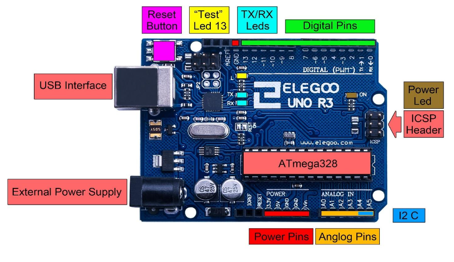
The Brain: The large black chip is the ATmega328P microcontroller.
The Power/Program Port: The USB port you're connected to.
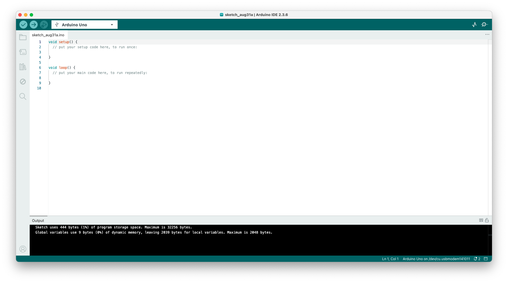
The Arduino IDE
The Integrated Development Environment is where you'll write, check, and upload your code.
Open it up now. Let's make sure it's set up for your board.
First Time Setup in the IDE
Before you can upload code, you need to tell the IDE what you're using.
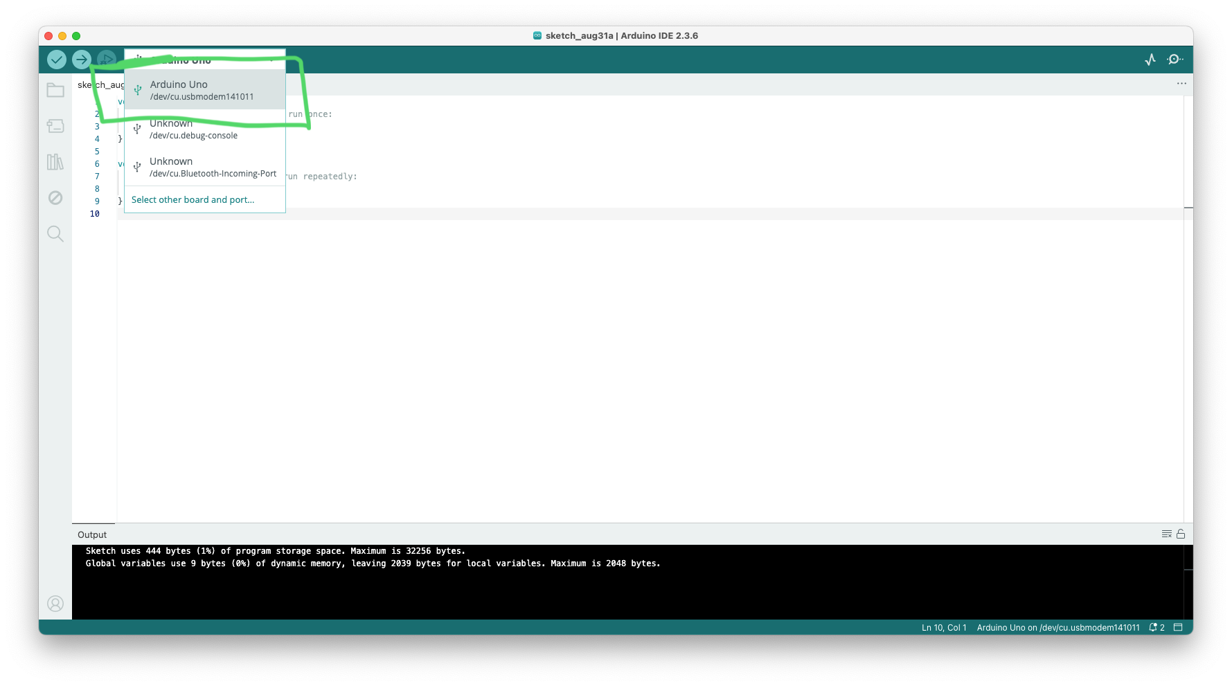
- Go to Tools > Board and make sure "Arduino Uno" is selected.
- Go to Tools > Port and select the port your Arduino is connected to. It will likely have "(Arduino Uno)" next to it. (e.g., COM3 on Windows, /dev/cu.usbmodem... on Mac).
This is the most common point of failure. If you can't upload, always check these two settings first!
The Two Most Important Buttons
1. Verify (✓): Compiles your code. It checks for syntax errors, just like in C++. It doesn't send anything to the board.
2. Upload (→): First, it verifies your code. If there are no errors, it sends the compiled program to your Arduino board to run.
Arduino C vs. C++
Good news! You've been learning C++ for 6 weeks. The Arduino language is just a set of C++ functions and libraries.
This means you already know:
- Variables (int, float, bool)
- Control Structures (if, else)
- Loops (for, while)
- Functions
The main difference is the program structure.
// You know all this!
int count = 0;

for (int i = 0; i < 10; i++) {
  count += i;
}

if (count > 40) {
  // do something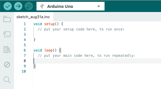
}The Two Essential Functions
Every Arduino program (called a "sketch") must have two functions:
setup()
- Runs once when the board powers on or is reset.
- Used for initialization (e.g., setting up pins).
loop()
- Runs continuously after
setup()finishes. - This is where the main logic of your program goes.
// This code runs only one time
void setup() {
  // Put your setup code here
}

// This code runs over and over, forever!
void loop() {
  // Put your main code here
}Your First Target: The Onboard LED
Every Arduino Uno has a built-in Surface-Mount LED labeled 'L'.
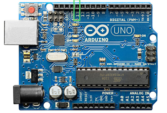
This LED is internally connected to Digital Pin 13. By controlling Pin 13, we can control this LED. It's the perfect way to test if our code is working!
Controlling Pins: The 3 Key Functions
To control a pin (like the one for our LED), we need to know three basic commands.
pinMode(pinNumber, MODE)
Tells the Arduino if a pin will be an INPUT or an OUTPUT. We use this insetup().digitalWrite(pinNumber, VALUE)
Sets an output pin's voltage to be either HIGH (5V, On) or LOW (0V, Off).delay(milliseconds)
Pauses the program for a specified amount of time. (1000ms = 1 second).
Code Breakdown: `pinMode()`
In our setup() function, we must declare Pin 13 as an output pin, because we want to send a signal *out* to the LED.
The Arduino also has a built-in variable, LED_BUILTIN, which is a convenient way to refer to Pin 13.
Using LED_BUILTIN makes our code more portable to other types of Arduino boards.
void setup() {
  // Set the built-in LED pin (13) as an output.
  pinMode(LED_BUILTIN, OUTPUT);
}

void loop() {
  // Main code will go here...
}Code Breakdown: `digitalWrite()` & `delay()`
Inside our infinite loop(), we will perform a sequence of actions:
- Turn the LED on.
- Wait for one second.
- Turn the LED off.
- Wait for one second.
Then, because it's in a loop, this sequence will repeat forever!
void loop() {
  // Turn the LED on (HIGH is the voltage level)
  digitalWrite(LED_BUILTIN, HIGH);

  // Wait for a second
  delay(1000);

  // Turn the LED off by making the voltage LOW
  digitalWrite(LED_BUILTIN, LOW);

  // Wait for a second
  delay(1000);
}Let's Code: The "Blink" Sketch
Time to get your hands dirty!
Type the complete code on the right into your Arduino IDE. You can also find it under File > Examples > 01.Basics > Blink.
Once you've typed it in:
- Click Verify (✓) to check for errors.
- If it's okay, click Upload (→).
Watch your board. The 'L' LED should start blinking!
// The complete "Blink" sketch

void setup() {
  // initialize digital pin LED_BUILTIN as an output.
  pinMode(LED_BUILTIN, OUTPUT);
}

void loop() {
  digitalWrite(LED_BUILTIN, HIGH);   // turn the LED on
  delay(1000);                       // wait for a second
  digitalWrite(LED_BUILTIN, LOW);    // turn the LED off
  delay(1000);                       // wait for a second
}Challenge: Modify the Blink!
Congratulations, you're now a microcontroller programmer!
Let's experiment. Try to make the following changes to your code and upload again after each one:
- Make the LED blink faster. (e.g., twice a second).
- Make the LED stay on for a long time (2 seconds) and off for a short time (200 milliseconds).
- What happens if you remove one of the
delay()calls?
This is the core of physical computing: write code, upload, and see the result in the real world.
A Guided Tour of the Pins
Now that you've used a pin, let's understand the different groups of pins on your board.
We'll look at each section one by one.
Power Pins
These pins don't run code, they provide electricity.
- GND: "Ground". This is the 0 Volt reference point for your circuits. You need to connect this to complete a circuit. You have three of them.
- 5V: A regulated 5 Volt supply. Most common components use this.
- 3.3V: A regulated 3.3 Volt supply for more sensitive components.
- VIN: "Voltage In". You can power the Arduino through this pin using an external power source (like a 9V battery).
Analog In Pins (A0 - A5)
These are special "listening" pins.
- They are INPUTS ONLY.
- Unlike digital pins that only see HIGH or LOW, these pins can measure a range of voltages between 0V and 5V.
- They convert the voltage they "read" into a number between 0 (for 0V) and 1023 (for 5V).
- Perfect for reading sensors that give a variable signal, like a light sensor or a temperature sensor.
Digital Pins (0 - 13)
These are the general-purpose workhorses.
- Each can be configured as an INPUT or an OUTPUT.
- As outputs, they can only be HIGH (5V) or LOW (0V). This is what we used for our LED.
- As inputs, they can detect if something is HIGH or LOW (e.g., reading if a button is pressed).
- Special Pins: 0 (RX) and 1 (TX) are used for serial communication (talking to the computer). It's best to avoid using them for now.
PWM Pins (~ 3, 5, 6, 9, 10, 11)
Notice the tilde symbol (~) next to some of the digital pins?
These are special digital pins that can simulate an analog output. This is called Pulse Width Modulation (PWM).
- Instead of just HIGH or LOW, they can create an effect that is "in-between".
- They do this by switching on and off very, very quickly.
- This is useful for things like dimming an LED or controlling the speed of a motor.
- We use the function
analogWrite(pin, value)where value is 0-255.
Getting Feedback: The Serial Monitor
How can we see what our Arduino is thinking? Or print the value of a variable for debugging?
The Serial Monitor is a text window in the Arduino IDE that lets the Arduino send messages back to your computer over the USB cable.
It is an absolutely essential tool for debugging your code!
You can open it by clicking the magnifying glass icon in the top-right of the IDE.
Using the Serial Monitor
To use it, you need two new commands:
Serial.begin(9600);
- Initializes serial communication. The number 9600 is the "baud rate" (data speed).
- Put this in your
setup()function.
Serial.println("Hello!");
- Prints a line of text to the Serial Monitor.
- You can also print variables:
Serial.println(myVariable);
void setup() {
  // Start serial communication at 9600 bits per second:
  Serial.begin(9600);
}

void loop() {
  // Print a message and wait a second
  Serial.println("Hello from my Arduino!");
  delay(1000);
}Challenge: Count with the Serial Monitor
Let's combine what we know.
Write a sketch that:
- Creates a global integer variable called
counterand initializes it to 0. - In the
setup(), initializes the Serial Monitor. - In the
loop(), it prints the current value ofcounter, incrementscounterby 1, and waits for half a second.
Upload the code and open the Serial Monitor. You should see a list of numbers counting up.
Challenge: Count with the Serial Monitor
Let's combine what we know.
Write a sketch that:
- Creates a global integer variable called
counterand initializes it to 0. - In the
setup(), initializes the Serial Monitor. - In the
loop(), it prints the current value ofcounter, incrementscounterby 1, and waits for half a second.
Upload the code and open the Serial Monitor. You should see a list of numbers counting up.
// Your counting code here!
int counter = 0;

void setup() {
  Serial.begin(9600);
}

void loop() {
  Serial.print("Count: ");
  Serial.println(counter);
  counter++; // or counter = counter + 1;
  delay(500);
}Serial: More Than Just `println()`
The Serial object is your powerful communication link to the computer.
We've used Serial.println() which prints data and then adds a new line character (like hitting Enter).
There's also Serial.print() which prints data without moving to the next line.
This is extremely useful for building up messages on a single line before finishing with a println().
int sensorValue = 123;

void loop() {
  // Use print() to build the line
  Serial.print("Sensor Value: ");
  Serial.print(sensorValue);
  Serial.print(" | Time: ");

  // Use println() to finish the line
  Serial.println(millis());
  delay(1000);

  // Output looks like:
  // Sensor Value: 123 | Time: 4567
}Sending Formatted Data
You can print almost any data type: int, float, char, and strings.
Serial.print() can also take a second argument to change the number base for integer types.
- DEC for Decimal (base 10) - This is the default.
- BIN for Binary (base 2).
- HEX for Hexadecimal (base 16).
- OCT for Octal (base 8).
int value = 65;

void setup() {
  Serial.begin(9600);

  Serial.print("Decimal: ");
  Serial.println(value, DEC); // Prints "65"

  Serial.print("Hex: ");
  Serial.println(value, HEX); // Prints "41"

  Serial.print("Binary: ");
  Serial.println(value, BIN); // Prints "1000001"

  Serial.print("Character: ");
  Serial.println((char)value); // Prints "A"
}
void loop() {} Receiving Data: Time to Listen
Your Arduino can also receive data sent from the Serial Monitor. This makes your projects interactive!
Serial.available()
- Checks if any data has been sent from the computer.
- Returns the number of bytes (characters) waiting to be read.
- Use it in an
ifstatement:if (Serial.available() > 0)
Serial.read()
- Reads one character from the incoming data.
- You must call this inside a
Serial.available()check.
void loop() {
  // Is there any data waiting for us?
  if (Serial.available() > 0) {
    // Yes! Let's read the first character.
    char incomingByte = Serial.read();

    // Now we can do something with it...
    Serial.print("I received: ");
    Serial.println(incomingByte);
  }
}Example: A Simple Serial "Echo"
This sketch demonstrates two-way communication.
It waits for you to type something into the Serial Monitor and press Send.
It then reads what you sent, one character at a time, and "echoes" it back to the monitor.
This is a fundamental pattern for creating command-based projects.
void setup() {
  Serial.begin(9600);
  Serial.println("Send me a message and I will echo it!");
}

void loop() {
  // if there's any serial data available
  if (Serial.available() > 0) {
    // read the incoming character:
    char incomingChar = Serial.read();

    // echo it back to the serial monitor:
    Serial.print("You sent: ");
    Serial.println(incomingChar);
  }
}Recap: What We Learned Today
- The Arduino is a microcontroller board that runs one program in a loop.
- Every sketch needs a
setup()function (runs once) and aloop()function (runs forever). - We can control the built-in LED using Pin 13 (
LED_BUILTIN). - Key functions:
pinMode(),digitalWrite(), anddelay(). - The pins are grouped into Power, Analog In, and Digital.
- The Serial Monitor is our best friend for debugging and seeing what the Arduino is doing.