Introduction
Welcome to the world of electronics! In this lab, you will learn the basics of building and programming a simple circuit without needing any physical parts. We will use a fantastic free tool called Autodesk Tinkercad.
What you will learn:
- How to navigate the Tinkercad Circuits editor.
- To identify and use basic electronic components like an Arduino, LED, and a resistor.
- How to connect components to build a circuit.
- The basics of programming an Arduino to control an output.
Part 1: Getting Started with Tinkercad
First, we need to set up your workspace.
- Open your web browser and go to www.tinkercad.com.
- If you have an account, click "Sign in". If you don't, ask your teacher for the class code or create a free personal account.
- Once you are logged in, you will be on your main dashboard. On the left-hand menu, click on "Circuits".
- Click the big green button that says "+ New" (or "Create new Circuit").
You should now see the Tinkercad Circuits editor. This is your virtual workbench!
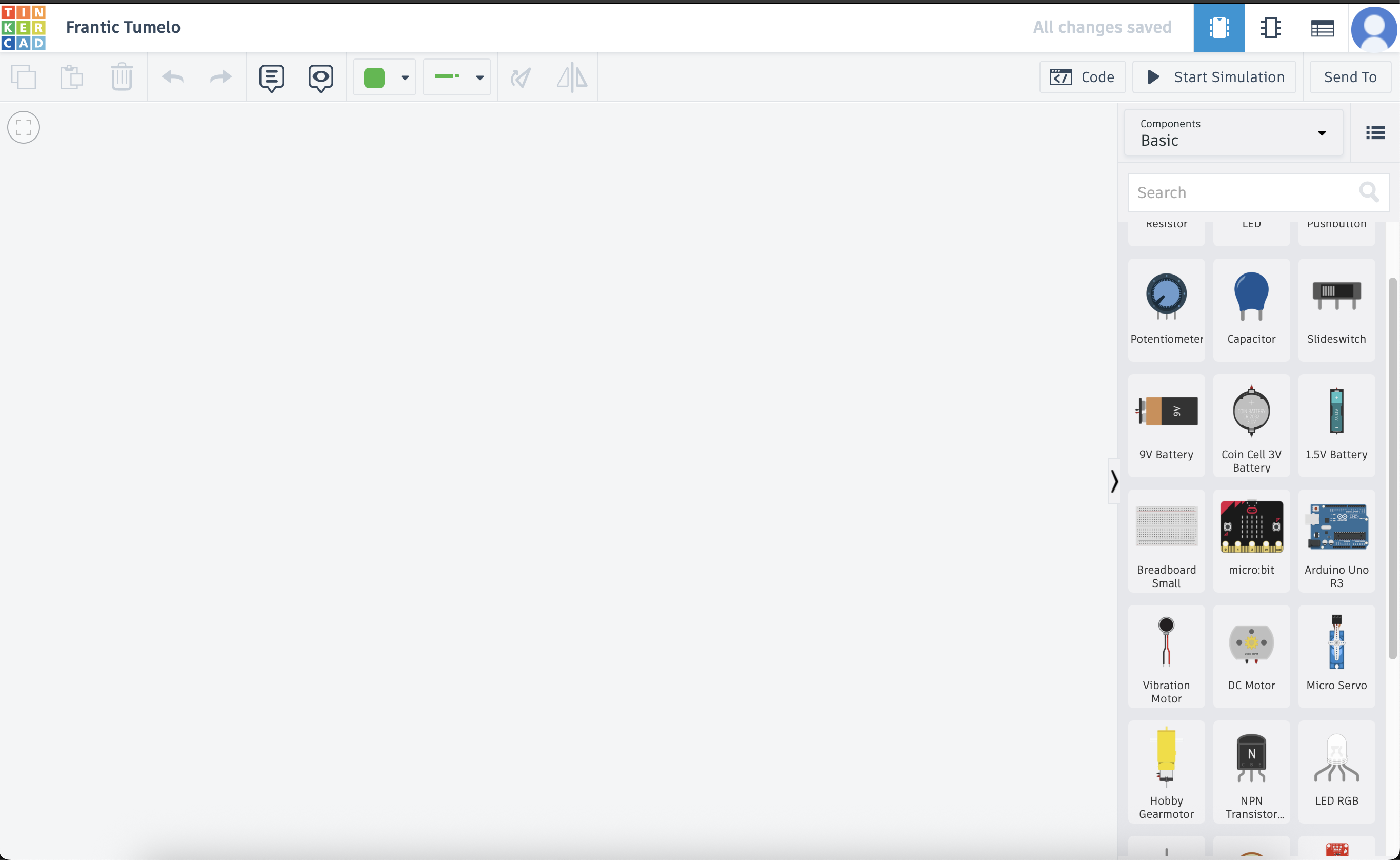
Part 2: Building the Circuit
Now for the fun part! We will build a circuit to light up an LED. We need three components from the panel on the right:
- Arduino Uno R3: The "brain" of our project.
- LED: A small light.
- Resistor: This protects our LED from getting too much power.
- Add the Arduino: Find the "Arduino Uno R3" in the components list and drag it onto your workplane.
- Add the LED: Find the "LED" and drag it onto the workplane. Notice it has two legs. If you hover over them, one is named Anode (+) (the bent leg) and the other is Cathode (-) (the straight leg).
-
Add the Resistor: Find the "Resistor" and drag it onto the workplane. We need to change its value. Click on the resistor, and a small window will pop up. Change the Resistance to 220 and make sure the unit is set to Ω (Ohms).
Why a resistor? An LED can't handle the full power from the Arduino. The resistor limits the current, acting like a gatekeeper to protect the LED from burning out.
-
Wire it all up! We will now connect everything with virtual wires. To create a wire, simply click on a connection point (it will highlight in red) and then click on another connection point.
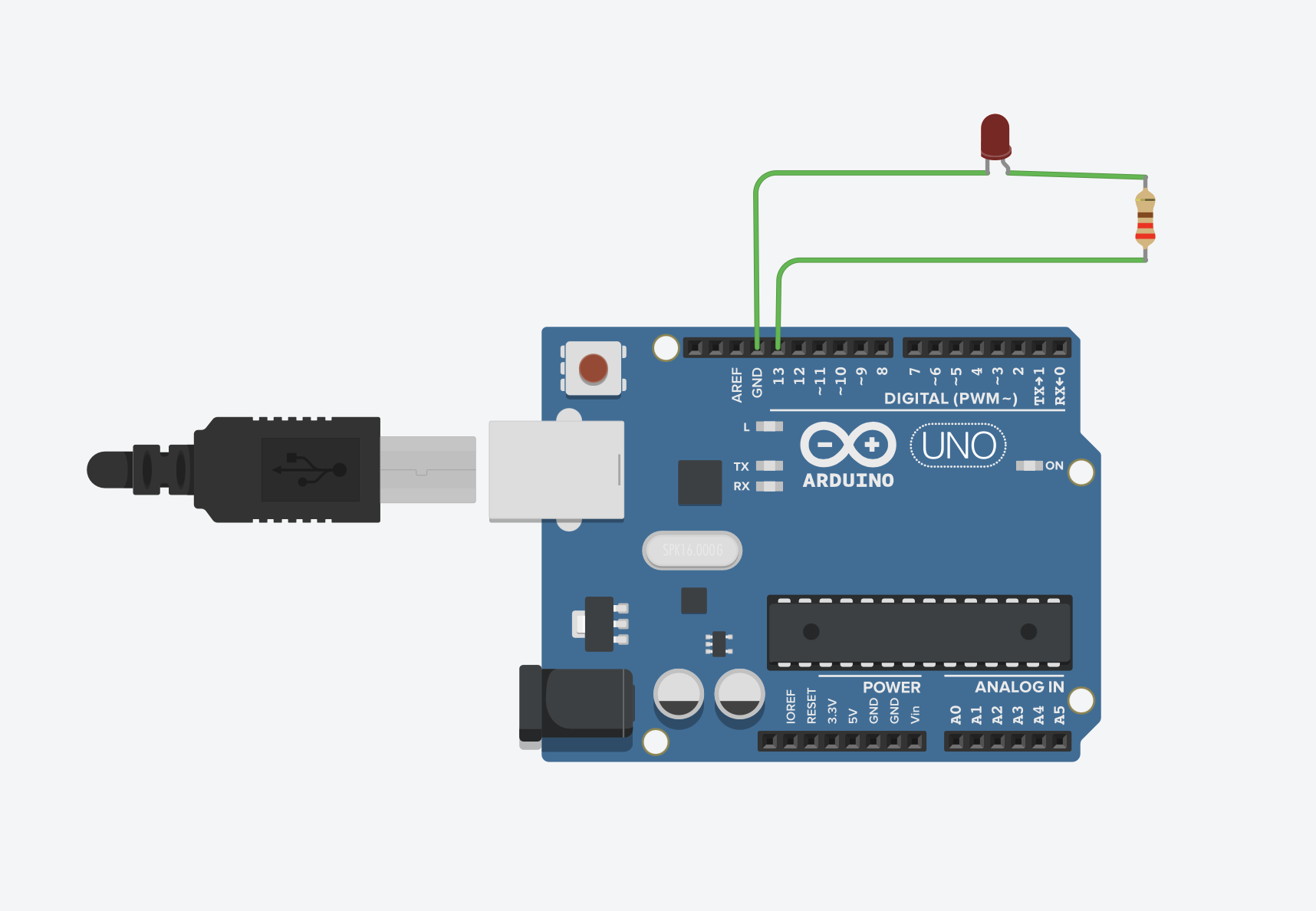
- Step A: Connect the resistor to the LED. Click on one end of the resistor and drag a wire to the Anode (+) leg of the LED.
- Step B: Connect the resistor to the Arduino's power. Click on the other end of the resistor and drag a wire to the digital pin labeled 13 on the Arduino.
- Step C: Connect the LED to the Arduino's ground. Click on the Cathode (-) leg of the LED and drag a wire to one of the pins labeled GND (which stands for Ground) on the Arduino.
Your final circuit should look something like this:
Part 3: Writing the Code
Now we need to tell the Arduino what to do. We'll write a simple program to turn the LED on and off.
- At the top right of the screen, click the "Code" button. The code editor will slide out.
- By default, Tinkercad uses a "Blocks" editor. This is perfect for beginners. If it says "Text" at the top, click the dropdown and change it to "Blocks".
- There might be some default blocks already there. You can drag them to the trash can icon to start fresh.
-
The Logic: We want to create a program that does the following, forever:
- Turn the LED ON.
- WAIT for 1 second.
- Turn the LED OFF.
- WAIT for 1 second.
-
Build the Block Code:
- From the Output category (blue), drag the `set pin [0] to HIGH` block into the `forever` loop. Change the `0` to `13`, since that's the pin we connected our LED to. `HIGH` means ON.
- From the Control category (orange), drag the `wait [1] seconds` block and place it right under the first block.
- From the Output category again, drag another `set pin [0] to HIGH` block underneath the wait block. Change the `0` to `13` and change `HIGH` to `LOW`. `LOW` means OFF.
- Finally, from the Control category, drag one more `wait [1] seconds` block and place it at the very bottom.
Your final block code should look like this:

Bonus: See the Real Code!
Click the "Blocks" dropdown menu at the top of the code panel and select "Blocks + Text". You will now see the text-based code (written in C++/Arduino) that your blocks created. This is what real-world Arduino programming looks like!
// C++ code
//
void setup()
{
  pinMode(13, OUTPUT);
}

void loop()
{
  digitalWrite(13, HIGH); // Turn the LED on
  delay(1000); // Wait for 1000 milliseconds (1 second)
  digitalWrite(13, LOW);  // Turn the LED off
  delay(1000); // Wait for 1000 milliseconds (1 second)
}
Part 4: Run Your Project!
This is the moment of truth. Let's run our simulation to see if it works.
- If the code panel is open, you can click the "Code" button again to hide it and see your full circuit.
- Click the "Start Simulation" button in the top right corner.
If everything is connected correctly, the small LED on your virtual circuit should start blinking on and off, once every second!
Congratulations!
You have successfully built and programmed your first electronic circuit. You are now officially a maker!
Troubleshooting
If it doesn't work, don't worry! This is a normal part of engineering. Click "Stop Simulation" and check these common issues:
- Wiring: Is the wire from the resistor definitely going to pin 13? Is the wire from the cathode (short leg) of the LED definitely going to GND?
- LED Direction: Is the LED facing the right way? The resistor should be connected to the Anode (+, bent leg).
- Code: Double-check your blocks. Is the pin number set to 13 in all the blocks?
Challenges & Next Steps
Now that you know the basics, try experimenting!
- Change the Speed: Go back into the code and change the `wait` time from `1` second to `0.5` seconds. What happens? Try a very short time, like `0.1`.
- Use a Different Pin: Stop the simulation. Move the wire from pin `13` to pin `8`. Now, change the pin number in your code from `13` to `8`. Run the simulation again. Does it still work?
- Add a Second LED: Can you add a second LED (with its own resistor) to another pin (like pin `12`) and make them blink at the same time? Or, can you make them alternate?